- Product Name
- Product Keyword
- Product Model
- Product Summary
- Product Description
- Multi Field Search
 |


| Quantity: | |
|---|---|
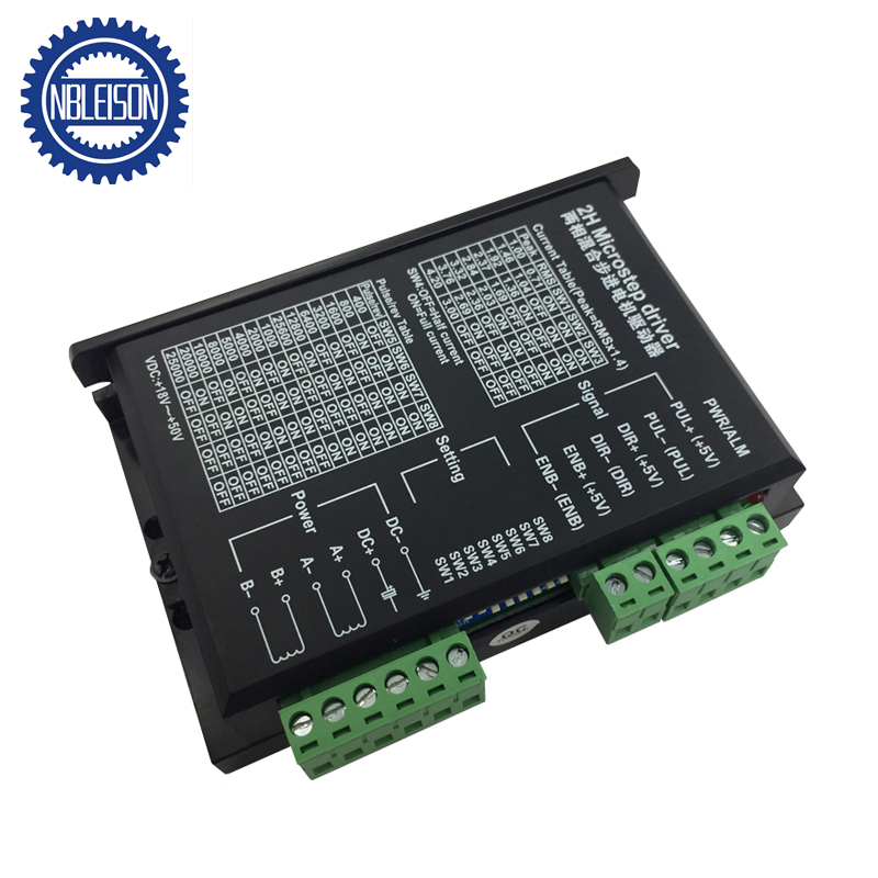
M542
Leison Motor
Stepper motor driver specificaiton:
Introduction:
M542-type sub-type of two-phase hybrid stepping motor driver, DC power supply for drive voltage 20V ~ 50V, current is less than 4.0A, 42 〜86mm diameter two-phase hybrid steppingmotor. This drive by AC servo drive current loop subdivision control, the motor torque ripple is small, low-speedm, smooth running, low vibration and noise. High speed, relatively high output torque, high precision positioning. Widely used in engraving machines, CNC machine tools, packaging machinery, transmission equipment and other devices that require a higher resolution.
Features:
1. Average current control, two-phase sinusoidal output current drive
2. DC 24 ~ 50V power supply
3. Opto-isolated input / output
4. Overvoltage, undervoltage, overcurrent, short circuit protection phase
5. Subdivision sixteen files and automatic half current function
6. Eight stalls set the output phase current
7. With offline capabilities
8. High speed start
9. High-speed torque
Electrical parameters:
| Input Voltage | DC20〜50V Input |
| In put Current | <4A |
| Output Current | 1.0A 〜4.2A |
| Power | Power: 80W ; Internal Insurance: 6A |
| Temperature | Operating: -10〜45C; Storage: -40 C 〜70"C |
| Humidity | Not condensation, water droplets can not have |
| Gas | Prohibition of combustible gases and conductive dust |
| Weight | 200G |
Control signal interface
Figure 1 is a wiring diagram drive
1. The control signal definitions
PLS+: Positive In put pulse signal
PLS-: Negative pulse signal in put
DIR+: Positive sign al input termi nal step di recti ons
DIR-: Negative signal in put step directions
ENA+: offline enabli ng the reset signal in put is terminal
ENA-: offline enabling the reset signal input negative terminal
Offline enable signal is active reset drive failure, and no effective pulse, the output power of the drive components is closed, no motor to maintain torque.
2. The control signals connections
PC active high control signal can also be active low. When active high, the control signal to the negative side of all connected together as a
signal, the low effective, all control signals are connected together as a signal common. Now and PNP open collector output, for example, in terface
circuit diagram is as follows:

Note:
VCC is 5V, R shorted;
VCC is 12V, R is 1K, more than 1/8W resistance;
VCC is 24V, R for the 2K, more than 1/8W resistor;
R must be connected to the controller terminals.
Function selection(With the drive to achieve on the panel DIP switch,see Figure 1)
1. set the number of motor steps per revolution Drives the motor, respectively, the number of steps per revolution is
set to 200,400,500,800,1000,1250,1600,2000,2500,3200,4000,5000,6400,8000,10000,12800 step. You can drive through the front panel DIP switch SW5, SW6, SW7, SW8 bit to set the drive number of steps (Table 1):
| SW5 | OFF | ON | OFF | ON | OFF | ON | OFF | ON | OFF | ON | OFF | ON | OFF | ON | OFF |
| SW6 | ON | OFF | OFF | ON | ON | OFF | OFF | ON | ON | OFF | OFF | ON | ON | OFF | OFF |
| SW7 | ON | ON | ON | OFF | OFF | OFF | OFF | ON | ON | ON | ON | OFF | OFF | OFF | OFF |
| SW8 | ON | ON | ON | ON | ON | ON | ON | OFF | OFF | OFF | OFF | OFF | OFF | OFF | OFF |
| Pulse/rev | 400 | 800 | 1600 | 3200 | 6400 | 12800 | 25600 | 1000 | 2000 | 4000 | 5000 | 8000 | 10000 | 20000 | 25000 |
| Table 1 | |||||||||||||||
2. control mode
DIP switches SW4-bit control can be set into two:
Set to "OFF" when, as a semi-streaming capabilities.
Set to "ON" when, for no half-streami ng capabilities.
3. set the output phase current
The different torque to drive the stepper motor, the user can drive the panel DIP switch SW1, SW2, SW3 bit to set the drive's output phase current (RMS) per ampere, the switch position corresponds to the output current, different models drive output current corresponding to different values. Detailed in Table 2.
| Output Current (A) | ||||
| SW1 | SW2 | SW3 | PEAK | RMS |
| ON | ON | ON | 1.00 | 0.71 |
| OFF | ON | ON | 1.46 | 1.04 |
| ON | OFF | ON | 1.91 | 1.36 |
| OFF | OFF | ON | 2.37 | 1.69 |
| ON | ON | OFF | 2.84 | 2.03 |
| OFF | ON | OFF | 3.31 | 2.36 |
| ON | OFF | OFF | 3.76 | 2.69 |
| OFF | OFF | OFF | 4.20 | 3.00 |
| Table 2 | ||||
4. the semi-flow function
Semi-flow function is non-500ms after the step pulse, the driver output current automatically reduced to 70% of rated
output current, is used to prevent motor heat.
Power Interface
1. AC1, AC2, PE: connect the drive power
220VAC in put power supply voltage is the maximum current is 5 A. Power line cross-section > 1.5 square mm, as short
as possible. Driver side and AC2 AC1 termi nation power supply, while external to series with a 6A fuse. PE grou nd
terminal.
2. A + A-B + B-: to link the two-phase hybrid stepping motor
Drive and two-phase hybrid steppi ng motor connected by four-wire system, the motor win dings in parallel and series
connection, and connection method, high-speed performa nee, but the drive curre nt (the motor win ding curre nt 1.73
times), the series connection When the drive current is equal to the motor winding current.
Note: If the power supply without isolation transformer, the need to drive PE ground terminal and the motor reliable
grounding.
Installation
To have 20mm of space around, can not be placed next to other heating devices, to avoid dust, oil mist, corrosive gas,
humidity, vibration is too large and strong places.

Troubles and its shotting ways
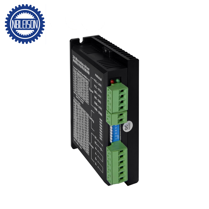
1. the status lights indicate
RUN: green, normal work light.
ERR: red, light failure, the motor phase short circuit, overvoltage and undervoltage, drive over temperature (heat sink
temperature exceeds 75 degrees.)
2. Troubles
| Failure | Reason | Solutions |
| LED off | Pick the wrong power supply | Check the power conn ection conn ection |
| Low supply voltage | Improve the power supply voltage | |
| Motor does not turn, and not to keep the torque | Electrical connections not | Correct motor connections |
| RESET signal to enable the effective offline | The RESET is not valid | |
| Motor does not turn, but maintain the torque | No pulse signal input | Adjust the pulse width and signal level |
| The direction of moter rotation error | Pick the wrong phase sequence power lines | Swap any two connected lines |
| Right direction signal input | Change the direction set | |
| Motor torque is too small | Too small relative to current setting | Phase current is set correctly |
| Acceleration too fast | Reduce the acceleration | |
| Motor stall | Ruled out mechanical failure | |
| Does not match with the motor drive | For a suitable driver |
Drive wiring
A complete stepper motor control system with stepper drives, DC power supply and controller (pulse source).
The following is a typical system wiring diagram:

Stepper motor driver specificaiton:
Introduction:
M542-type sub-type of two-phase hybrid stepping motor driver, DC power supply for drive voltage 20V ~ 50V, current is less than 4.0A, 42 〜86mm diameter two-phase hybrid steppingmotor. This drive by AC servo drive current loop subdivision control, the motor torque ripple is small, low-speedm, smooth running, low vibration and noise. High speed, relatively high output torque, high precision positioning. Widely used in engraving machines, CNC machine tools, packaging machinery, transmission equipment and other devices that require a higher resolution.
Features:
1. Average current control, two-phase sinusoidal output current drive
2. DC 24 ~ 50V power supply
3. Opto-isolated input / output
4. Overvoltage, undervoltage, overcurrent, short circuit protection phase
5. Subdivision sixteen files and automatic half current function
6. Eight stalls set the output phase current
7. With offline capabilities
8. High speed start
9. High-speed torque
Electrical parameters:
| Input Voltage | DC20〜50V Input |
| In put Current | <4A |
| Output Current | 1.0A 〜4.2A |
| Power | Power: 80W ; Internal Insurance: 6A |
| Temperature | Operating: -10〜45C; Storage: -40 C 〜70"C |
| Humidity | Not condensation, water droplets can not have |
| Gas | Prohibition of combustible gases and conductive dust |
| Weight | 200G |
Control signal interface
Figure 1 is a wiring diagram drive
1. The control signal definitions
PLS+: Positive In put pulse signal
PLS-: Negative pulse signal in put
DIR+: Positive sign al input termi nal step di recti ons
DIR-: Negative signal in put step directions
ENA+: offline enabli ng the reset signal in put is terminal
ENA-: offline enabling the reset signal input negative terminal
Offline enable signal is active reset drive failure, and no effective pulse, the output power of the drive components is closed, no motor to maintain torque.
2. The control signals connections
PC active high control signal can also be active low. When active high, the control signal to the negative side of all connected together as a
signal, the low effective, all control signals are connected together as a signal common. Now and PNP open collector output, for example, in terface
circuit diagram is as follows:
Note:
VCC is 5V, R shorted;
VCC is 12V, R is 1K, more than 1/8W resistance;
VCC is 24V, R for the 2K, more than 1/8W resistor;
R must be connected to the controller terminals.
Function selection(With the drive to achieve on the panel DIP switch,see Figure 1)
1. set the number of motor steps per revolution Drives the motor, respectively, the number of steps per revolution is
set to 200,400,500,800,1000,1250,1600,2000,2500,3200,4000,5000,6400,8000,10000,12800 step. You can drive through the front panel DIP switch SW5, SW6, SW7, SW8 bit to set the drive number of steps (Table 1):
| SW5 | OFF | ON | OFF | ON | OFF | ON | OFF | ON | OFF | ON | OFF | ON | OFF | ON | OFF |
| SW6 | ON | OFF | OFF | ON | ON | OFF | OFF | ON | ON | OFF | OFF | ON | ON | OFF | OFF |
| SW7 | ON | ON | ON | OFF | OFF | OFF | OFF | ON | ON | ON | ON | OFF | OFF | OFF | OFF |
| SW8 | ON | ON | ON | ON | ON | ON | ON | OFF | OFF | OFF | OFF | OFF | OFF | OFF | OFF |
| Pulse/rev | 400 | 800 | 1600 | 3200 | 6400 | 12800 | 25600 | 1000 | 2000 | 4000 | 5000 | 8000 | 10000 | 20000 | 25000 |
| Table 1 | |||||||||||||||
2. control mode
DIP switches SW4-bit control can be set into two:
Set to "OFF" when, as a semi-streaming capabilities.
Set to "ON" when, for no half-streami ng capabilities.
3. set the output phase current
The different torque to drive the stepper motor, the user can drive the panel DIP switch SW1, SW2, SW3 bit to set the drive's output phase current (RMS) per ampere, the switch position corresponds to the output current, different models drive output current corresponding to different values. Detailed in Table 2.
| Output Current (A) | ||||
| SW1 | SW2 | SW3 | PEAK | RMS |
| ON | ON | ON | 1.00 | 0.71 |
| OFF | ON | ON | 1.46 | 1.04 |
| ON | OFF | ON | 1.91 | 1.36 |
| OFF | OFF | ON | 2.37 | 1.69 |
| ON | ON | OFF | 2.84 | 2.03 |
| OFF | ON | OFF | 3.31 | 2.36 |
| ON | OFF | OFF | 3.76 | 2.69 |
| OFF | OFF | OFF | 4.20 | 3.00 |
| Table 2 | ||||
4. the semi-flow function
Semi-flow function is non-500ms after the step pulse, the driver output current automatically reduced to 70% of rated
output current, is used to prevent motor heat.
Power Interface
1. AC1, AC2, PE: connect the drive power
220VAC in put power supply voltage is the maximum current is 5 A. Power line cross-section > 1.5 square mm, as short
as possible. Driver side and AC2 AC1 termi nation power supply, while external to series with a 6A fuse. PE grou nd
terminal.
2. A + A-B + B-: to link the two-phase hybrid stepping motor
Drive and two-phase hybrid steppi ng motor connected by four-wire system, the motor win dings in parallel and series
connection, and connection method, high-speed performa nee, but the drive curre nt (the motor win ding curre nt 1.73
times), the series connection When the drive current is equal to the motor winding current.
Note: If the power supply without isolation transformer, the need to drive PE ground terminal and the motor reliable
grounding.
Installation
To have 20mm of space around, can not be placed next to other heating devices, to avoid dust, oil mist, corrosive gas,
humidity, vibration is too large and strong places.
Troubles and its shotting ways
1. the status lights indicate
RUN: green, normal work light.
ERR: red, light failure, the motor phase short circuit, overvoltage and undervoltage, drive over temperature (heat sink
temperature exceeds 75 degrees.)
2. Troubles
| Failure | Reason | Solutions |
| LED off | Pick the wrong power supply | Check the power conn ection conn ection |
| Low supply voltage | Improve the power supply voltage | |
| Motor does not turn, and not to keep the torque | Electrical connections not | Correct motor connections |
| RESET signal to enable the effective offline | The RESET is not valid | |
| Motor does not turn, but maintain the torque | No pulse signal input | Adjust the pulse width and signal level |
| The direction of moter rotation error | Pick the wrong phase sequence power lines | Swap any two connected lines |
| Right direction signal input | Change the direction set | |
| Motor torque is too small | Too small relative to current setting | Phase current is set correctly |
| Acceleration too fast | Reduce the acceleration | |
| Motor stall | Ruled out mechanical failure | |
| Does not match with the motor drive | For a suitable driver |
Drive wiring
A complete stepper motor control system with stepper drives, DC power supply and controller (pulse source).
The following is a typical system wiring diagram:


